Load |
您所在的位置:网站首页 › rampage iv extreme 3930k oc › Load |
Load
|
Load-Line Calibration (LLC) Behavior Part 2: now with more science! (Read part 1 here) Necroed with permission from Windspeed36.
So as fun as it was to be featured on the WAN show, I took particular offense to Linus saying that it wasn’t the most scientific thing ever. As a BSc (Chemistry) and a current MSc student, it was now a point of honor to do a better job. Luckily, I got a new motherboard, so I have an excuse to try again!
In my previous post/article/report (whatever you want to call it), I outlined how LLC behaves at different settings while at idle and load. I drew attention to the fact that higher values of LLC will result in a massive voltage jump going from idle to load. In this sense I think I can agree with Linus’ “lack of science” statement, where I just didn’t record enough readings. So here I am trying again, expanding the testing range, and performing statistical analyses on the data collected. Before I get too into the nitty-gritty details, I do want to briefly touch on why this is important. When you pull your motherboard out of the box, LLC will (in all likelihood) be set to AUTO. The unfortunate thing about the AUTO setting for overclocking, is that you don’t know what it will do. Frequently the AUTO setting will dynamically choose a setting based on what you’re doing. This is why people always recommend doing your own overclocking as opposed to clicking the “automatically overclock” button. Imagine, if you will, yourself trying to get an overclock with AUTO selected for LLC. What if your motherboard chooses Ultra High or Extreme as the auto setting? How much extra voltage is it applying under load? Is that voltage degrading your CPU more than you think it is? These questions illustrate why manually setting your LLC is important in overclocking.
Note to the reader: if you don't care how I did it, you can simply just skip to the Conclusions section to get the important information.
Testing Setup: ASUS Rampage IV Black Edition, i7 3930k, 16 GB Corsair Vengeance CL8 (CMZ8GX3M2A1600C8) ram in quad-channel configuration, XFX PRO 1000W PSU, Corsair H100i cooling. Again, my multiplier was set to 40 (stock is 32), and I ran a voltage sweep from 1.250-1.400V in 0.005V increments (expanded from my sweep of 1.325-1.400V from last post). Voltages were applied using the ASUS AI Suite 3 (I’m too lazy to reboot between each voltage change). Voltage was first swept at idle (1.250-1.400V), then swept at load for each LLC setting. As with my previous motherboard, the R4BE has five settings for LLC: Regular (0%), Medium (25%), High (50%), Ultra High (75%), and Extreme (100%). Voltage readings were taken using the ProbeIt voltage read points on the motherboard, using a digital multimeter. Idle voltages were taken while Windows 7 was running at the desktop with no programs open, and load voltages were taken with Prime95 small FFT’s running. Voltage readings were taken whenever possible, but voltages greater than 1.410V were a stopping point for me, and much of the load sweep for Regular LLC was unstable, so readings could not be taken in some ranges.
Data Analysis: Linear regression analyses (Microsoft excel LINEST function) were performed on the obtained data to determine the trends within each sweep. I will present the data in chart format here for illustration, but raw data and LINEST output can be viewed here. For those who haven’t taken a statistics class, a linear regression generates a line-of-best-fit, which can be used to predict values outside of the tested range, provided that the calculated line fits the data well. Regression outputs for the Idle and Load will be presented directly below the respective legend titles. Each output will include the equation of the regression line (in the format y={slope}x + {intercept} and can be used as the calculation {voltage read} = {slope}*{voltage set} + {intercept}). Below each equation of the line is an “r-squared” value, which gives an indication of how well the calculated line fits the data obtained. A high r-squared (>0.98, say) indicated that the line is a very good fit to the data.
Results:
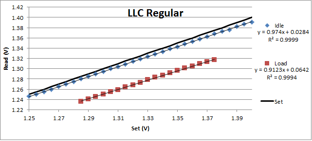
At the LLC setting of Regular (0%), we again see an idle voltage lower than set, although not as much of a drop as it was on the RIVE. With only looking at the output of this chart we see that the lines look pretty straight, and there is a reasonable droop going from idle to load. The interesting part of this chart comes from looking at the linear regression output. One would expect the read voltage to increase in a linear fashion with set voltage with a 1:1 ratio. For each incremental increase of set voltage, I would expect the read voltage to increase by that same increment. That is to say, I would expect the slope of each of these lines to have a value of 1. This is not the case. Looking closely at the data, both the idle and load slopes are not equal to one, and in fact are less than one, meaning that each unit increase does not add the full 5mV to the read voltage. Also, the slope decreases going from idle to load.
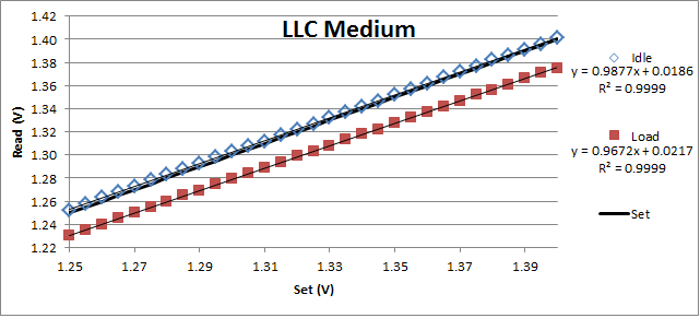
At the LLC setting of Medium (25%), the idle voltage tracks reasonably closely to the set value, but there is a voltage droop when going to load. The slopes of these trendlines are still not equal to 1, but they are closer to 1 than the trendlines of LLC Regular.
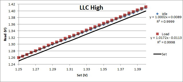
At the LLC setting of High (50%), both the idle and load voltages are slightly higher than the set values, but are notably very similar going from idle to load. Also, the slopes of the trendlines are now greater than one, indicating that we should expect more voltage per unit set than less at this LLC setting. These slopes are now the most similar to 1:1, and the intercepts are the closest to zero of all the LLC settings.
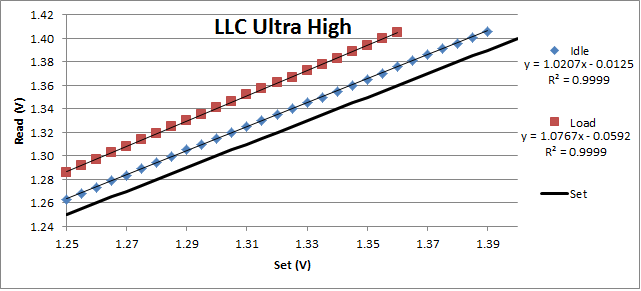
At the LLC setting of Ultra High (75%), we can now see an appreciable boost in voltage from set at both idle and load. Following the emerging trend, the slopes of the trendlines are increasing with increasing LLC setting, and the slopes are now decidedly greater than the expected 1.
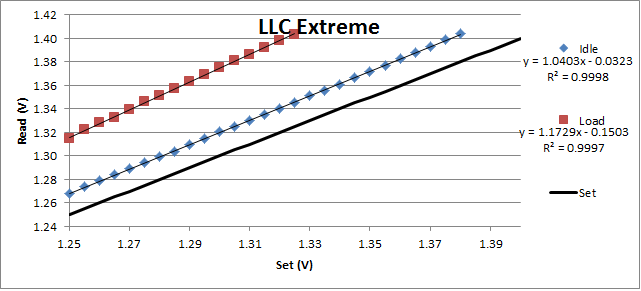
At the LLC setting of Extreme (100%), there is a significant boost in voltage from set at both idle and load. The slope of the load line is now significantly higher than 1, adding a much greater voltage than the user set. It should also be noted that the r-squared values are decreasing ever so slightly as compared to the other LLC settings. This indicates that although the voltages should still be largely predictable, they are more likely to deviate from predicted by a few mV.
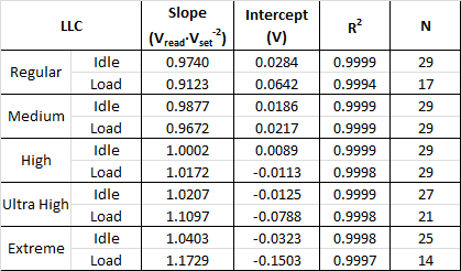
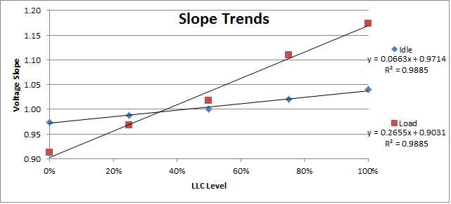
The resulting slopes can be nicely grouped into a pretty table, and the slopes can be plotted to see that the observed trend of increasing slope with increasing LLC setting holds true. Unfortunately the linear behaviour of the lines isn’t perfect, but we can clearly see that the load slopes increase much more significantly with LLC setting than the idle slopes.
In the last post, I stated that the CPU voltage changes with the CPU frequency, but I wanted to back this up with some actual data. Since modifying the base clock of the CPU is now a much less utilized overclocking technique, I instead modified the CPU multiplier. I set a manual voltage of 1.300V at LLC High, and increased the multiplier from 12-40 while under load. As we can see from the data, there is a slight increase of voltage with increased multiplier setting. No doubt, this data would be much more linear in fashion if I had a multimeter that had increments of 0.1 mV instead of 1 mV. The voltage only increases by 3 mV over the whole multiplier range, so effectively one could expect the read voltage to not drift significantly.
Conclusions: I can see that the assertion I made in the previous post that there are exact vdroop or vboost values for each LLC setting is incorrect. Instead, it may be better to say that one can predict the effective (read) voltage at a particular LLC value and set voltage. Now I did not test the entire range of voltages (this would not be practical), but it seems that over the useful voltage range of CPU vcore, the idle and load voltages follow a linear trend. This means that the behaviour of the CPU voltage can be exactly known and combinations of LLC and Vcore can be logically chosen to achieve an effective voltage to stabilize an overclock. For instance, to achieve a multiplier of 45 on my CPU, I need 1.325V effective vcore. This means, using the equations of the lines obtained from my analysis, I can solve for the required vcore setting at each LLC value. In this example, to achieve a 1.325V load vcore, I would need to set 1.382, 1.348, 1.314, 1.265, or 1.258V at LLC Regular, Medium, High, Ultra High, and Extreme respectively. Of course, I would need to validate whether the idle voltages would be sufficient to stabilize the multiplier. I plan to test this assertion in a follow up series of tests, and I’ll likely post the results somewhere on this forum. How is this applicable to you, the reader? You could perform your own series of tests to determine the behaviour of your LLC on your motherboard. The nice thing about what I’ve done here is that I’ve proven that read voltage increases linearly with set voltage with a consistent slope, so all you need to test is a minimum of three voltages on each setting to determine your LLC line behaviour. Obviously, for increasing accuracy, more readings should be taken, but if you take three readings across your effective vcore range, you should be able to predict any voltage reading across and outside of that range at idle or load for any LLC setting you choose (to within a few mV). LLC is a powerful and necessary tool to consider while overclocking. I hope that this thread illustrates that one can approach LLC in a logical fashion, as opposed to thinking of it as a magic voodoo setting. One can logically choose an LLC setting appropriate to their overclock with only a few measurements, which should help to keep a consistent and known voltage.
TL;DR: It’s important to manually set LLC while overclocking. Additionally, one can do a simple series of tests to determine their motherboard’s LLC behaviour at idle and load, and logically select their LLC setting to fit their overclocking needs. |

【本文地址】